Capacitive Phasor Diagram
Phasor reactance capacitive inductive imaginary diagram resistance why axis real component stack Transformer on load condition Phasor capacitor diagram current voltage chapter ppt powerpoint presentation
Phasor diagram showing different positive-sequence currents I and
Diagram transformer load phasor capacitive vector condition draw circuit vectorified Phasor diagram of capacitor supported dvr. Capacitor diagram phasor ac circuit circuits parallel series
Phasor capacitor dvr supported
Phasor diagram showing different positive-sequence currents i andPhasor fault currents different Phasor diagram for capacitive and inductive modePhasor sssc capacitive illustrating compensation.
Series circuit rc phasor diagram vector impedance draw phase circuits power ckt voltages multiply why which capacitor finding when curvePhasor diagram illustrating statcom operation in capacitive Ac capacitance inductance phasor diagram circuit inductive capacitive reactance analysis gif physics emoLaw capacitors impedance ohm phasor form inductors dummies ohms generalize expand put.

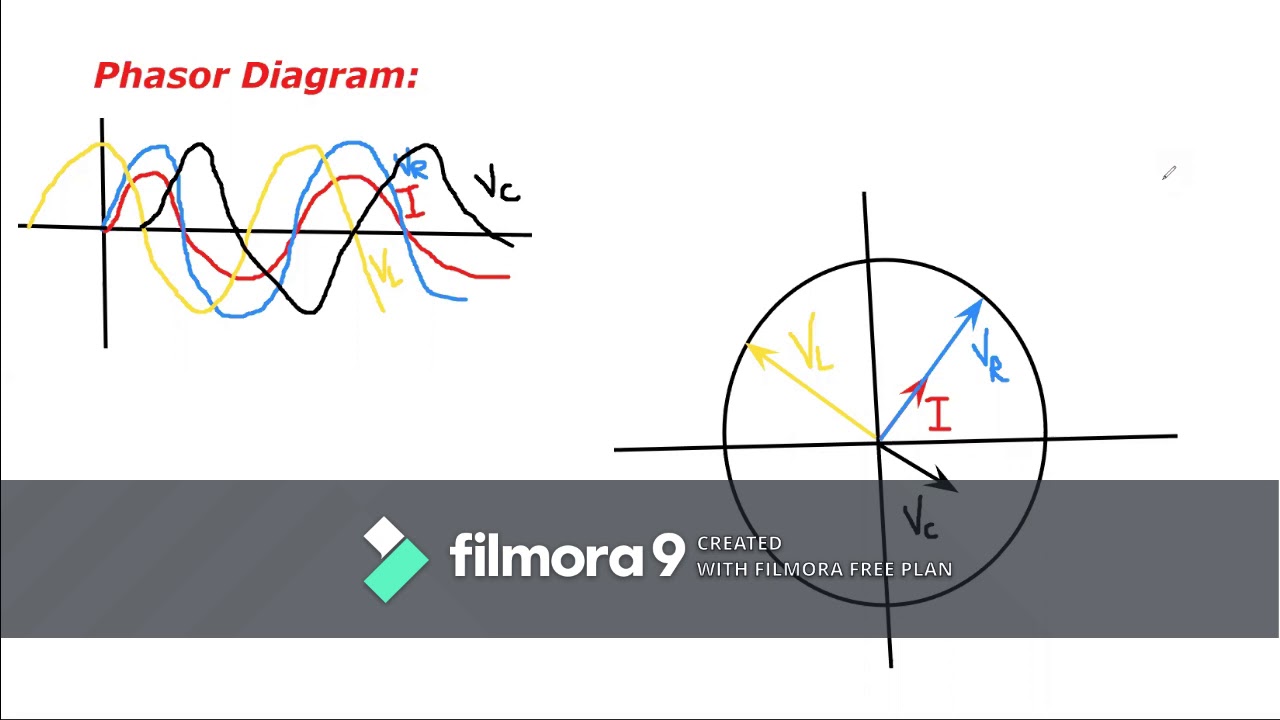
Phasor inductive capacitive mode
What is rc series circuit? phasor diagram and power curveCapacitor circuits: capacitor in series, parallel & ac circuits What is a pure capacitor circuit?Phasor and the phasor diagram in ac circuits explained.
Waveform capacitor phasor capacitiveAc capacitance and capacitive reactance in ac circuit Generalize impedance to expand ohm’s law to capacitors and inductorsPhasor rlc draw impedance fasor sirkuit vc rangkaian seri circuitglobe.

Phasor circuits
What is rlc series circuit?Solved given: the phasor circuit shown above. required: Why is the inductive reactance or capacitive reactance phasor on theCircuit phasor series rlc reactance inductive diagram voltage capacitive parallel analysis impedance vector electrical reference source constant axis imaginary why.
Why is the inductive reactance or capacitive reactance phasor on the .


Why is the inductive reactance or capacitive reactance phasor on the

PPT - Chapter 33 PowerPoint Presentation, free download - ID:517471

Solved Given: The phasor circuit shown above. Required: | Chegg.com

Generalize Impedance to Expand Ohm’s Law to Capacitors and Inductors

What is RC Series Circuit? Phasor Diagram and Power Curve - Circuit Globe

Phasor diagram showing different positive-sequence currents I and

Phasor diagram illustrating STATCOM operation in capacitive
Phasor and The Phasor Diagram in AC Circuits Explained - YouTube

Phasor diagram for capacitive and inductive mode | Download Scientific