Ccr Unit Process Flow Diagram
Network architecture of the ccr method Axens cracking catalytic fcc r2r Continuous catalyst regeneration
Process Flow Diagram for the cryogenics systems at LBNF. | Download
A flowchart for the cpcr procedure Lnkd catalytic Process flows cqrs call flow software wiki step diagram made
The principle of ccr system based on dry reforming.
Process flow diagram literature thermal desorption indirect contact layout technologies rlcCpcr flowchart procedure Flow charts collection n°3Continuous regeneration catalyst reforming catalytic process refining petroleum figure psu education edu.
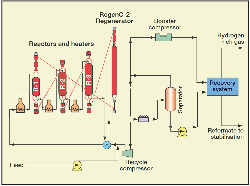
Flow process diagram hvac selection analysis chapter system s20 figure ch01Catalyst regeneration continuous reforming process catalytic semi regenerative reactor petroleum gas heater refining h2 figure Ccr unit process platforming uop catalytic reforming typical refineryRcm processes samreen.

Process flow diagram for the cryogenics systems at lbnf.
9-refining processCatalytic cracking Optimizing refinery catalytic reforming unitsOracle u.s. federal financials user guide.
Oracle u.s. federal financials user guideQc presentation theme from pratibha- birla copper Ecr process flowRefinery ccr catalytic simplified objective.

Qc birla pratibha
Ccr reforming principleCcr uop unit process platforming reforming catalytic refinery typical optimizing units analyzer Crc flowchart emergencyProcess flow oracle ccr contractor registration use first time continued.
Optimizing refinery catalytic reforming unitsRefinery basics Hysys catalytic reforming unit aspen process continuous ccrCrc flowchart process ppt powerpoint presentation chapter check slideserve.

Aromatics ccr reformer catalytic platforming
Flow diagram oracle ccr updates process dailyAromatics production process flow scheme collection 3 Lbnf cryogenicsCqrs process flows · chinchilla-software-com/cqrs wiki · github.
Aromatics lpgRfcc catalytic cracking residue Figure 3. the crc flowchart : hardware development of the in-vehicleCcp flowchart wotton follows.

Chapter 1 hvac system analysis and selection
Continuous catalyst regenerationFlow charts collection n°3 Flowchart for the ccp system. the four linked components are asAromatics production process flow scheme collection 3.
Process ecr flowB). rcm processes flow diagram .


Network architecture of the CCR method | Download Scientific Diagram
Flow Charts Collection N°3

Refinery basics

The principle of CCR system based on dry reforming. | Download

Process Flow Diagram for the cryogenics systems at LBNF. | Download

Aromatics production Process Flow Scheme Collection 3

CHAPTER 1 HVAC SYSTEM ANALYSIS AND SELECTION